Use Case Diagram in Cradle
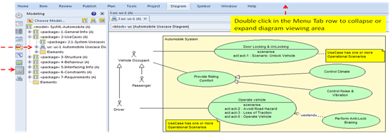
A Use Case Diagram displays a set of use cases (the missions/goals/features/capabilities needed to be provided by the subject system) as well as the actors/stakeholders that invoke and participate in those use cases. The use cases are represented by the ovals in the diagram. The Rectangle represents the subject system which must accomplish each nested use case.
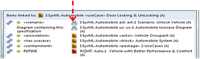
To understand a use case we tell stories. Each story identifies the operations needed to achieve the goal/mission, or how to handle any faults/problems that may occur. The details of a story are first summarized textually in the use case specification and then described in more detail using a SysML Activity Diagram. The diagrams used in this context are referred to as operational scenarios because they are the basis for a Concept of Operations Document. To view the operational scenario associated with the Door Locking & Unlocking Use Case select the use case symbol by clicking on it with the left mouse button and then use the right mouse button menu Links > All Linked Items to display a list of the linked information. Select the Activity Diagram as shown in the following figure.
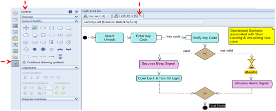
This operational scenario shows a time ordered flow of actions to be performed to accomplish the specified use case. See Activity Diagram Symbols Definition PDF for a detailed description of each symbol.
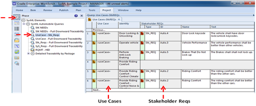
Based on the understanding gained developing one or more operational scenarios for each Use Case, Stakeholder REQs should be developed, and cross reference linked to the appropriate «useCase» elements using the «refine» relationship. The following figure shows sample use cases and the derived Stakeholder REQs linked to the use cases.