Block Definition Diagram in Cradle
1.There are two kinds of SysML Diagrams used to specify the structure of the proposed System (i.e., Block Definition Diagrams and Internal Block Definition diagrams). A block used in either type of diagram is a type of 'thing' (e.g., system, subsystem, light, report, organization, human, etc).
Based on the understanding gained defining the use cases and the various operational scenarios, a system context diagram is usually created first to identify the external systems (man-made and natural environment) the subject system of interest may interact with. The SysML Block Definition Diagram (bdd) shown below is used to identify the interfacing external systems using the hollow diamond symbol connector.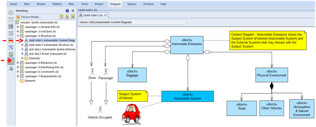
The filled in diamond symbol identifies the component parts of a thing and the hollow diamond symbol identifies referenced/shared things that may interact with a subject block.
The block symbol has several compartments that can be displayed by checking the box in the Diagram Control Sidebar. In the following example the flow properties and operations compartments are displayed for the selected block (i.e., Automobile System).
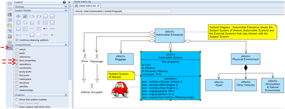
The contents of the compartments are specified by linking stereotype elements to the block element. This ensures that the information represents live SysML elements rather than plain text typed into a field. The cross referenced links can be seen in the Modeling Sidebar as show in the following figure.
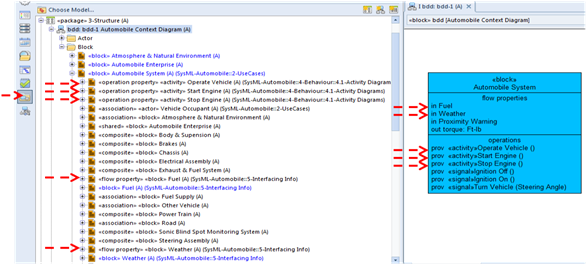
The following bdd diagram shows the structure of the Automobile System Block one level down the system hierarchy using the filled in diamond symbol.
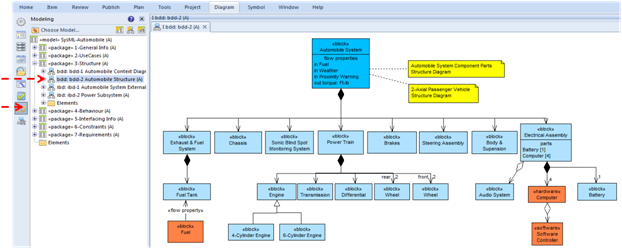
There are several examples where another level of component parts are shown such as the Automobile System to Power Train to Engine, Transmission, Differential, rear Wheels, and front Wheels. Also the diagram has an example of a generalization symbol (hollow triangle symbol) indicating the engine can be either a 4-Cylinder or a 6-Cylinder Engine.
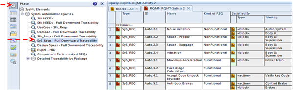
The blocks on the bdd should have assigned behavior, and linked Requirements. In the following figure you can see which System Requirements are assigned to which Blocks. Notice there are Functional and Non-Functional Requirements assigned to the Blocks defined on the bdd diagrams, and functional requirements assigned to behavior actions defined in Activity Diagrams. The following traceability table shows the system requirements linked to specific modeling elements.