
Internal Block Diagram in Cradle
The Internal Block Diagram is used to model the internal structure of a block and define the interconnections of the block’s component parts and the interactions (i.e., interface information) between the parts and between the parts and the outside world.
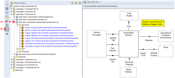
The following ibd diagram is used to identify interfacing information at the system level for the Automobile system. The dashed rectangles represent external systems and the Item Flows (arrow head symbols) on the connector paths specify interfacing information. The Item Flows drawn on the diagram are also displayed in the modeling sidebar.
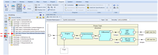
Another example ibd, shown below, identifies the parts of the Power Train and the interfacing information between those parts. In this example a compartment in the 'Power Train' symbol is used to show the component parts and interfaces of the 'Power Train'.
The internal Block Definition diagram is often used to show interlaces.