Activity Diagram in Cradle
There are three kinds of behavior diagrams: Activity, Sequence-Interaction, and State Machine diagrams. The Activity Diagram is used to model the behavior of each activity (i.e., operation) assigned to a «block» defined on a bdd diagram. The behavior specifies the transformation of inputs to outputs through a controlled time ordered sequence of actions. The Activity diagram is the primary representation for modeling flow-based behavior and is analogous to the widely used functional flow diagrams used for modeling system behavior.
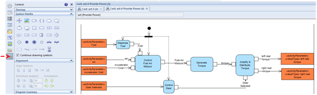
The actions are the rounded corner rectangles. The small squares attached to the edge of the action symbols are data objects (i.e., object nodes). These are blocks, signals, or value Type Input / Output (I/O) elements. The large rectangles are activity parameters that identify I/O for the diagram.
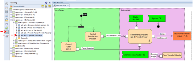
The action symbol with the ‘rake symbol’ in the lower right corner is a special action known as the ‘call behavior action’. It calls/invokes another behavior diagram (activity, sequence-interaction, or state machine). The called/invoked diagram can be viewed by double clicking on the symbol. The following figure shows the invoked Activity Diagram.