
Sequence-Interaction Diagram in Cradle
There are three kinds of behavior diagrams: Activity, Sequence-Interaction, and State Machine diagrams. Sequence-Interaction Diagrams are composed of Block/Actor Lifelinesand the MessageEventsthat get exchanged between the lifelines. The sequence diagram is particularly useful in modeling service-oriented processes where parts request services from other parts of the system.
The Lifelines on the diagram represent a structural element of a system or external system and its timeline. The structural element part of the Lifeline is depicted by a rectangle containing the name of the structural element. The timeline part of the Lifeline is depicted by a dashed line descending from the bottom of the rectangle, where time ‘advances’ from top to bottom.
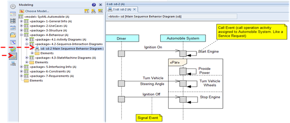
A message represents a Signal Event or a Call Event (request for service from the sending lifeline to the receiving lifeline). A Call Event message is shown on a sequence diagram as a line with a solid arrowhead. See ‘Start Engine’ in the following example. A Signal Event message (see ‘Ignition On’ in the following example) is shown on a sequence diagram as a line with an open arrowhead.
A combined fragment is shown on a Sequence-Interaction diagram using a frame that contains a label indicating the type of behavior (i.e., Alt, Opt, Par, and Loop) and the nested events that occur. In the following example a Parallel fragment (Par) has multiple regions containing events that occur in parallel. The parallel regions are separate by horizontal dashed lines.
In the following example the ‘Ignition On’ Signal is sent from the Driver Lifeline to the Automobile Lifeline. When that signal is received it causes the ‘Start Engine’ service (i.e., activity) to be performed. The Parallel fragment shows three Call Events that can occur in parallel because each one is in a separate region separated by a dashed line.
A key concept is that the lifeline structural elements and the message events are elements defined on other SysML diagrams and reused on the Sequence diagram. As the user integrates the use of these other elements together he/she can see whether or not they function together as desired.